Copper Busbar Manufacturing & Tolerances Current Carrying Capacity and CNC Bending & Water-Jet Machining Tolerance Standards for Round Edge vs. Square Copper Busbars in High-Voltage Switchboards

Precision fabrication of copper busbars directly dictates thermal efficiency, dielectric safety, and mechanical reliability in high-voltage switchboards. Choosing between round-edge and square-edge profiles changes not only the conductor’s ampacity and electric field distribution, but also its CNC bending and water-jet machining tolerance limits.
- Profile Selection: Full-round edge (C-edge) profiles minimize dielectric stress and corona discharge in high-voltage applications, while square profiles maximize surface contact area for bolting.
- CNC Bending: The standard minimum internal bend radius ($R$) should match busbar thickness ($T$) to prevent outer fiber cracking and cross-sectional thinning.
- Water-Jet Precision: Cold abrasive water-jet machining maintains tight tolerances ($\pm 0.1\text{ mm}$ to $\pm 0.2\text{ mm}$) without inducing a heat-affected zone (HAZ) or degrading electrical conductivity.
For critical energy infrastructure, adhering to precise fabrication standards is essential. Engineers can explore Zero-Defect Standard: The Quality Control Behind Costal’s Electrical Components to see how precision verification safeguards power assets.
Round Edge vs. Square Edge: Electrical & Thermal Performance
In high-voltage environments, geometry plays a vital role in field distribution. Square edges create concentrated electric field gradients at their sharp 90-degree corners. Under medium- and high-voltage conditions, these sharp boundaries significantly increase the risk of partial discharge and corona losses.
Round-edge busbars distribute the electric field evenly across the conductor perimeter. This profile reduces local dielectric stress and simplifies clearance requirements inside compact switchgear enclosures.
However, thermal dissipation and joint contact dynamics show different characteristics depending on the chosen geometry:
| Parameter | Square Edge Profile | Round Edge (Full Radius) Profile |
|---|---|---|
| Electric Field Concentration | High at corners (risk of corona) | Uniform distribution across perimeter |
| Bolted Joint Contact Area | 100% flat surface interface | Slightly reduced near outer chamfers |
| Skin Effect Distribution | Concentrated at outer corner edges | Smooth current density transition |
| Tooling & Bending Behavior | Prone to edge distortion/wrinkling | Even tensile and compressive flow |
When engineering high-density distribution systems, conductor geometry must integrate with surface treatments. For details on joint conductivity and plating, refer to The Science of Electrical Contact: Plating and Insulation Technologies in Modern Power Systems.
CNC Bending Tolerance Standards & Mechanical Limits
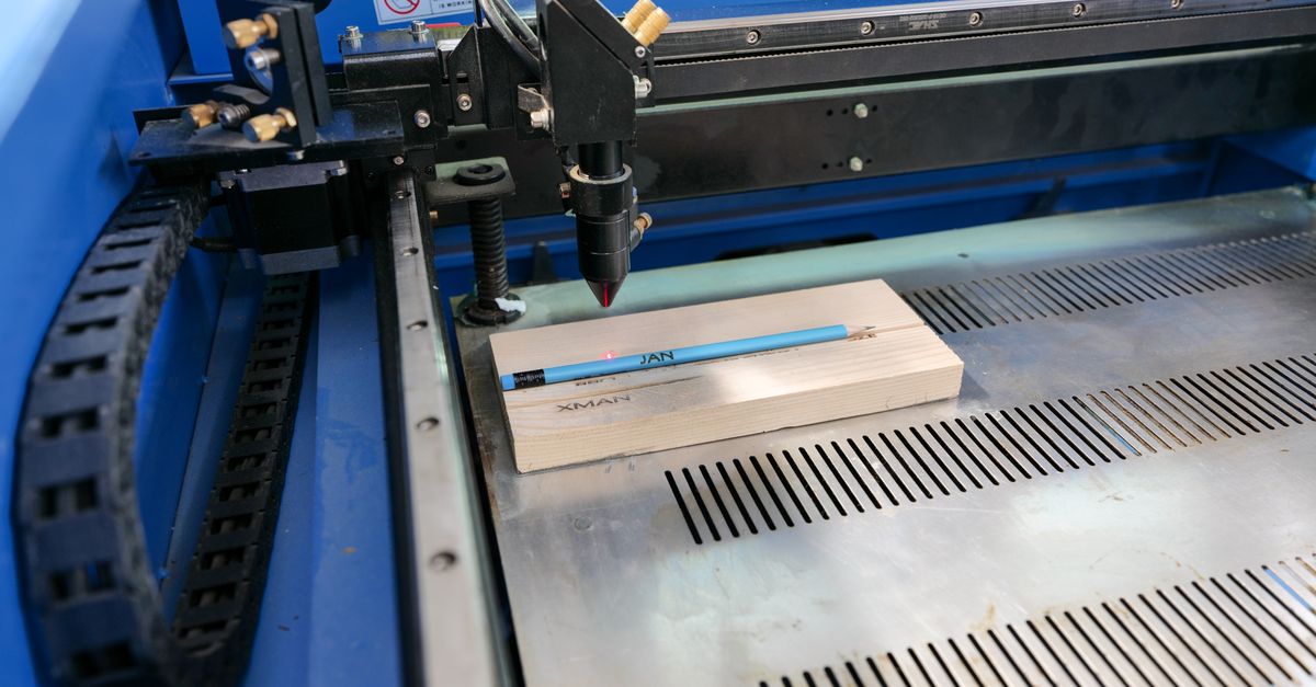
Cold forming high-conductivity copper (such as ETP or OFHC grades) requires strict control over bend geometry. Copper exhibits work hardening during CNC press brake operations, leading to predictable angular springback and localized material deformation.
- Minimum Bend Radius: Maintain $R_{inside} \ge 1.0 \times T$ for 90° bends to avoid micro-fracturing along the outer tension zone.
- Angular Tolerance: Standard CNC bending maintains $\pm 0.5^\circ$ for precision alignment across multi-tier busbar runs.
- Linear Dimension Tolerance: Hole-to-bend distance must respect a tolerance of $\pm 0.25\text{ mm}$ to prevent oval distortion at bolt locations.
- Thinning Allowance: Material thinning at the outer bend apex must not exceed 10% to 12% of nominal thickness to preserve current-carrying capacity.
Square-edge bars concentrate compressive stress along inner tooling contact lines, which can lead to lateral bulge and edge distortion. Round-edge bars flow smoothly through standard V-dies and rotary tooling, preserving structural integrity without creating sharp stress-concentration notches.
Maintaining an inside bend radius equal to or greater than the busbar thickness prevents localized conductor thinning and thermal hotspots.
Abrasive Water-Jet Machining Tolerances
Water-jet cutting is the preferred method for complex cutouts, phase-drop slots, and non-standard connection tabs. Unlike laser or plasma cutting, abrasive water-jet machining produces zero heat, completely eliminating thermal oxidation and annealing around cut edges.
This cold-cutting process preserves raw electrical conductivity and base material temper throughout the fabricated component:
Precision water-jet systems achieve linear positional tolerances of $\pm 0.1\text{ mm}$ to $\pm 0.15\text{ mm}$ across thicknesses up to 20 mm.
Dynamic 5-axis cutting heads compensate for jet stream lag, keeping edge taper under $0.05\text{ mm}$ for true perpendicular bolt seating.
Smooth abrasive cutting yields an edge finish of $Ra\ 3.2\ \mu\text{m}$ to $6.3\ \mu\text{m}$, reducing localized burrs and edge-arcing risks.
Maintaining tight hole and slot tolerances ensures that parallel busbars remain aligned during thermal expansion cycles. For complex utility installations, learn more about system compliance in Innovating Power Infrastructure: Certified Component Solutions for Global Utilities.
Current Carrying Capacity & Derating Factors
Continuous current-carrying capacity (ampacity) depends on cross-sectional area, surface emissivity, ambient temperature, and ventilation inside the switchboard. While square-edge bars have slightly larger cross-sectional area for the same nominal dimensions ($W \times T$), round-edge bars offer superior convection dynamics under enclosed conditions.
Engineers calculating busbar thermal ratings must apply appropriate correction factors:
- Base Ampacity Calculation: Determine nominal rating based on standard temperature rise limits (typically $\Delta T = 30\text{ K}$ or $50\text{ K}$ above ambient).
- Edge Profile Correction: Account for the approximate 2% to 4% cross-sectional reduction in full-round profiles compared to sharp square profiles.
- Surface Finish Factor: Bare copper has an emissivity of approximately 0.15, whereas tinned, silver-plated, or painted bars reach 0.70 to 0.90, allowing higher thermal dissipation.
- Multi-Bar Derating: Apply mutual heating derating factors ($0.8$ to $0.85$) when running parallel busbars separated by nominal bar thickness.
Frequently Asked Questions
Why is a round-edge profile preferred in high-voltage switchboards?
Round edges eliminate sharp 90-degree corners, creating a uniform electric field distribution that minimizes the risk of corona discharge and dielectric breakdown at high operating voltages.
What is the standard tolerance for CNC-bent copper busbars?
Standard CNC bending holds an angular tolerance of $\pm 0.5^\circ$ and linear hole-to-bend positional tolerances within $\pm 0.25\text{ mm}$ to ensure precise multi-tier switchboard alignment.
How does water-jet cutting compare to laser cutting for copper busbars?
Water-jet cutting is a cold mechanical process that creates no heat-affected zone (HAZ), avoiding oxidation, annealing, or local conductivity drops that can occur with high-reflectivity thermal laser cutting.
How does the minimum bend radius affect busbar ampacity?
Using a bend radius smaller than the busbar thickness causes extreme outer tensile thinning and micro-cracking, reducing cross-sectional area and creating high-resistance localized hotspots under continuous load.