Grounding Sleeves & Compression Tooling Dimension Selection Guide and Hydraulic Crimping Die Matching for KEPCO-Standard C-Type Ground Sleeves (SGW 22–325 sq mm)

In power distribution and substation construction, a grounding connection is only as reliable as its physical compression. Using the wrong die size or miscalculating the combined conductor cross-section in a C-type grounding sleeve can lead to loose bonds, elevated contact resistance, and dangerous ground fault failures.
For installations adhering to Korea Electric Power Corporation (KEPCO) standards, SGW-series C-type compression sleeves (ranging from 22 mm² to 325 mm²) provide a permanent, low-resistance tap or cross joint. However, achieving utility-grade mechanical strength and electrical continuity requires precise die matching and proper hydraulic tool operation.
- SGW Size Code: Corresponds to the combined cross-sectional area of the main run and tap conductors (e.g., SGW 70 accommodates 70 mm² total).
- Die Matching: Always match the die index stamped on the sleeve body with the hydraulic crimp die face.
- Hydraulic Pressure: Use a minimum 12-ton hydraulic compression head to guarantee cold-weld molecular bonding.
- Bite Sequence: Crimp from the center outward to prevent metal bowing and air pocket formation.
Understanding KEPCO-Standard C-Type Grounding Sleeves (SGW Series)
C-type grounding sleeves are open-faced, heavy-duty electrolytic copper connectors designed for parallel, tap, or cross grounding connections without cutting the continuous main conductor. Under KEPCO specifications, these connectors must withstand extreme fault currents while maintaining structural integrity underground or within cable trenches.
High-conductivity seamless copper provides excellent corrosion resistance and optimal thermal performance during transient ground surges. Reliable grounding networks often connect directly to primary distribution gear, where precision engineering like that found in certified component solutions for global utilities ensures long-term operational safety.
The open “C” shape allows technicians to hook the connector over an existing ground wire, slip the tap wire inside, and compress the assembly into a dense, solid copper mass using hydraulic force.
SGW Dimension Selection and Conductor Combination Guide
Choosing the correct SGW sleeve size requires calculating the total combined nominal area of the conductors placed inside the sleeve cavity.
The table below outlines common KEPCO-standard SGW models, typical conductor combinations (Main + Tap), and corresponding compression parameters:
| SGW Model | Total Conductor Range (mm²) | Typical Main + Tap Wire Combinations | Standard Die Index | Minimum Crimp Count |
|---|---|---|---|---|
| SGW-22 | 16 – 22 | 10 + 10 mm², 16 + 6 mm², 22 mm² single | CD-22 | 1 |
| SGW-38 | 25 – 38 | 22 + 16 mm², 35 + 2.5 mm², 38 mm² single | CD-38 | 2 |
| SGW-70 | 50 – 70 | 38 + 30 mm², 50 + 16 mm², 70 mm² single | CD-70 | 2 |
| SGW-100 | 75 – 100 | 70 + 30 mm², 50 + 50 mm², 95 mm² single | CD-100 | 3 |
| SGW-150 | 110 – 150 | 95 + 50 mm², 70 + 70 mm², 150 mm² single | CD-150 | 3 |
| SGW-200 | 160 – 200 | 120 + 70 mm², 95 + 95 mm², 185 mm² single | CD-200 | 3 |
| SGW-250 | 210 – 250 | 150 + 95 mm², 120 + 120 mm², 240 mm² single | CD-250 | 4 |
| SGW-325 | 260 – 325 | 185 + 120 mm², 150 + 150 mm², 300 mm² single | CD-325 | 4 |
Ensure that the total conductor volume fills at least 80% of the internal sleeve volume before crimping. Underfilled sleeves can cause loose contact, while overfilled sleeves lead to uneven die closure and mechanical flash.
Hydraulic Crimping Tool & Die Matching Principles
Standard manual crimpers cannot generate the tonnage required to deform thick-walled SGW copper sleeves. A 12-ton to 15-ton hydraulic crimping head (remote or battery-operated) is mandatory for SGW-70 and larger profiles.
- U-Type vs. C-Type Dies: Use dedicated C-groove or D3/CD-series dies shaped specifically to wrap the C-lip smoothly over the conductor.
- Manufacturer Verification: Ensure the die set radius aligns with KEPCO outer diameter specifications to prevent shearing the sleeve lips.
- Full Die Closure: Continue pumping the hydraulic tool until the bypass valve clicks or relief pressure is reached, ensuring full metal-to-metal die mating.
Strict tool calibration is vital across all electrical assemblies, from ground grids to high-power distribution where zero-defect electrical component quality control prevents catastrophic heating under heavy loads.
Step-by-Step Compression Procedure for Ground Grid Joints
Follow this standard installation sequence to achieve an airtight, corrosion-proof ground connection:
- Conductor Preparation: Strip insulation (if present) and vigorously wire-brush copper conductors to remove surface oxidation until bare, shiny copper is visible.
- Anti-Oxidant Application: Apply a light layer of conductive anti-oxidation paste inside the SGW sleeve cavity to seal out moisture.
- Conductor Placement: Position the continuous main grounding run at the base of the “C” cavity, then lay the branch or tap conductor firmly alongside it.
- Die Alignment: Position the hydraulic tool so that the fixed die supports the back spine of the C-sleeve and the moving die presses the open lips closed.
- Sequential Crimping: For sleeves requiring multiple crimps, make the first crimp at the center line, then alternate outward toward both edges.
- Visual Inspection: Check for full die closure, verify stamped index marks, and ensure no copper strand strands are pinched outside the sleeve boundary.
Common Field Mistakes and Troubleshooting
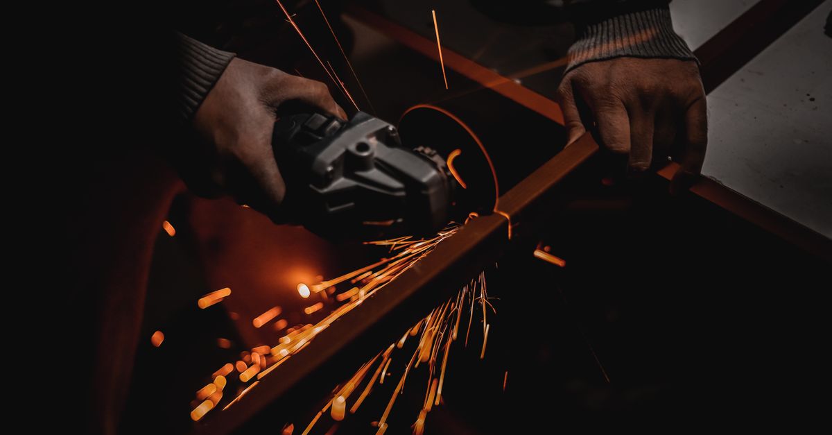
Using an oversized die leaves voids inside the joint, raising grounding resistance. Using an undersized die pinches copper fins (flash) that compromise wall thickness.
Old or oxidized copper develops high interface resistance. Without wire brushing, crimping seals in the oxide layer, causing hot spots during ground discharge.
Crimping edges first traps air inside the sleeve center and causes longitudinal banana warping, which damages nearby conductor strands.
A ground connection is only proven when the mechanical joint exhibits lower electrical resistance than an equivalent continuous length of the same conductor.
When engineering high-current facilities, the same precision applied to grounding must extend to distribution panels and custom switchgear designs, as detailed in our guide to custom fabrication demands in modern power transmission.
Frequently Asked Questions
Can I reuse an SGW C-type grounding sleeve if the crimp was misaligned?
No. Compression grounding sleeves undergo permanent plastic deformation during crimping. Re-crimping or opening a used sleeve damages the copper molecular structure, resulting in substandard pullout strength and elevated resistance.
How do I select an SGW sleeve when combining three wires in one tap?
Calculate the sum of the nominal cross-sectional areas of all three conductors (Main + Tap 1 + Tap 2). Select the SGW sleeve whose nominal rating equals or slightly exceeds this total sum, ensuring all conductors fit securely within the C-lip profile.
Is conductive anti-oxidation grease mandatory for underground C-sleeve joints?
Yes. Direct burial grounding joints are exposed to soil electrolytes and moisture. Applying an approved conductive anti-corrosion paste prevents galvanic oxidation between strands and maintains joint conductivity over decades of service.